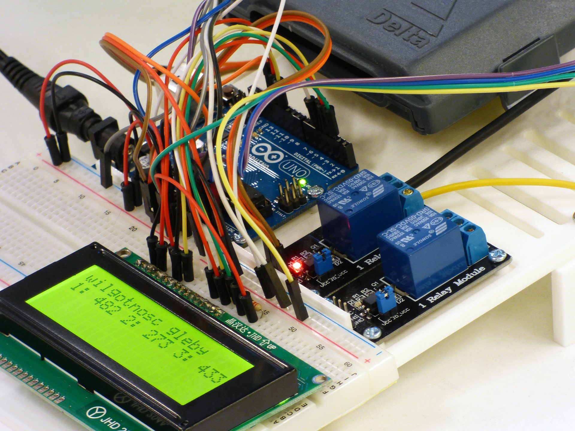
Are you new to the world of Arduino UNO and want to learn how to make an LED blink using it? Then you have come to the right place. In this blog, we will walk you through the steps involved in LED blinking with Arduino UNO.
Also, learn how make multiple LED blink using Arduino UNO.
What is Arduino UNO?
Arduino UNO is an open-source microcontroller board that is based on the ATmega328P microcontroller. It comes with digital input/output pins that can be used to connect to various sensors and devices. It also has an inbuilt USB interface, making it easy to connect it to a computer for programming and communication.
Components Required for LED Blinking Arduino UNO
For LED blinking with Arduino UNO, you will need the following materials:
- LED
- 220-ohm resistor
- BreadBoard
- Jumper Wires
- Arduino UNO Board
- USB Cables
Step 1: Connect the LED to the Breadboard
The first step in making LED blinking with Arduino UNO is to connect the LED to the breadboard.
Insert the long leg of the LED into a row of the breadboard and the short leg into the adjacent row.
Circuit Diagram

Step 2: Connect the Resistor
Next, connect the 220-ohm resistor to the breadboard. Insert one end of the resistor into the same row as the short leg of the LED and the other end into an empty row of the breadboard.
Step 3: Connect the Jumper Wires
Now it’s time to connect the jumper wires. Connect one end of the jumper wire to the digital pin 13 of the Arduino UNO board, and the other end to the same row as the resistor.
Connect another jumper wire to the same row as the long leg of the LED, and the other end to the ground (GND) pin of the Arduino UNO board.
Step 4: LED Blinking Code Arduino UNO
After connecting the hardware, it’s time to write the code for the Arduino UNO. Here’s the code that will make the LED blink:
void setup() {
  pinMode(13, OUTPUT);
}

void loop() {
  digitalWrite(13, HIGH);
  delay(1000);
  digitalWrite(13, LOW);
  delay(1000);
}
In the code above, we have defined the digital pin 13 as an output pin in the setup function. Then, in the loop function, we have used the digitalWrite function to turn the LED on (HIGH) and off (LOW) with a delay of 1 second (1000 milliseconds) in between.
Step 5: Upload the Code to Arduino UNO
After writing the code, it’s time to upload it to the Arduino UNO board. To do this, follow these steps:
- Connect the Arduino UNO board to your computer using the USB cable.
- Open the Arduino IDE software on your computer.
- Click on File > New to create a new sketch.
- Copy and paste the code from Step 4 into the new sketch.
- Click on Sketch > Upload to upload the code to the Arduino UNO board.
Step 6: See the LED Blinking Arduino UNO
Once the code is uploaded, you will see the LED blink on and off with a delay of 1 second in between. Congratulations, you have successfully made an LED blink with Arduino UNO!
References:
- Arduino UNO – https://www.arduino.cc/en/Guide/ArduinoUno
- LED Blinking Tutorial –


