In this blog post, we will guide you through the process of fading an LED using Arduino Uno. We will cover the basics of Arduino, introduce you to the concept of PWM, and provide a step-by-step guide with code examples.
What is Arduino?
Arduino is an open-source electronics platform based on easy-to-use hardware and software. It consists of a programmable circuit board and a software development environment that allows you to write and upload code to the board. Arduino boards are widely used by hobbyists, artists, and professionals to create interactive projects and prototypes.
What is PWM?
Pulse Width Modulation (PWM) is a technique used to control the amount of power delivered to an electronic device. It involves rapidly switching a signal on and off to create a digital signal with varying pulse widths. By changing the duty cycle of the signal, we can control the average power delivered to the device.
Fade an LED using Arduino Uno
Step 1: Gather the materials
To fade an LED using Arduino Uno, you will need the following materials:
- Arduino Uno board
- Breadboard
- LED
- Resistor (220 Ohm)
- Jumper wires
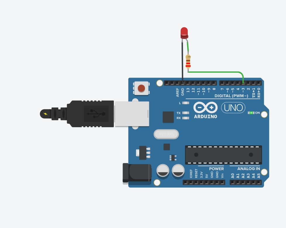
Step 2: Connect the circuit
Now that you have gathered all the materials, it’s time to connect the circuit. Follow the steps below:

- Connect the long leg of the LED (the positive leg) to pin 9 on the Arduino Uno board.
- Connect the short leg of the LED (the negative leg) to the breadboard.
- Connect one end of the 220 Ohm resistor to the short leg of the LED.
- Connect the other end of the resistor to the ground (GND) pin on the Arduino Uno board.
- Connect a jumper wire from pin 9 on the Arduino Uno board to the breadboard.
- Connect the other end of the jumper wire to a free row on the breadboard.
Step 3: Fading LED Arduino UNO Code
Now that the circuit is connected, it’s time to write the code. Open the Arduino IDE and follow the steps below:
- In the “Tools” menu, select “Board” and choose “Arduino/Genuino Uno”.
- In the “Tools” menu, select “Port” and choose the serial port of the Arduino Uno board.
- Open a new sketch in the Arduino IDE.
- Copy and paste the following code:
int ledPin = 9;    // LED connected to digital pin 9
int brightness = 0; // how bright the LED is
int fadeAmount = 5; // how many points to fade the LED by

void setup() {
  pinMode(ledPin, OUTPUT); // sets the pin as output
}

void loop() {
  analogWrite(ledPin, brightness); // sets the brightness of the LED
  brightness = brightness + fadeAmount; // changes the brightness
  if (brightness <= 0 || brightness >= 255) {
    fadeAmount = -fadeAmount; // reverses the direction of fading
  }
  delay(30); // waits for 30 milliseconds before continuing
}
- Click the “Upload” button to upload the code to the Arduino Uno board.
Step 4: Test the circuit
Now that the code is uploaded, it’s time to test the circuit. The LED should start to fade in and out. If it’s not working, check the circuit connections and make sure the code is uploaded correctly.
References:
- Arduino. (n.d.) https://docs.arduino.cc/
- Wikipedia. (2021). Pulse-width modulation https://en.wikipedia.org/wiki/Pulse-width_modulation
- Arduino. (n.d.). AnalogWrite https://www.arduino.cc/reference/en/language/functions/analog-io/analogwrite/
- Arduino. (n.d.). Digital Pins https://www.arduino.cc/en/Tutorial/DigitalPins